Tokyo Metropolitan College Of Technology
| |
| Home |
| Research |
| Facility |
| Publication |
| Member |
| Contact |
MPW Technique
|
A typical MPW system includes a power supply, which contains a bank of capacitors, a fast switching system and a coil. The parts to be joined are inserted into the coil, the capacitor bank is charged and the low inductance switch is triggered by a pulse trigger system and the current flows through the coil. When current is applied to the coil, a high-density magnetic flux is created around the coil, and as a result an eddy current is created in the work-pieces. The eddy currents oppose the magnetic field in the coil and a repulsive force is created. This force can drive the work-pieces together at an extremely high rate of speed and creates an explosive or impact type of weld. For more conductive metals such as aluminium and copper, the less energy is required to achieve a weld. The conventional MPW method with solenoidal coil is used for joining tubular parts and its features are almost well known. However, a few researches on MPW of sheet work-piece have been reported.
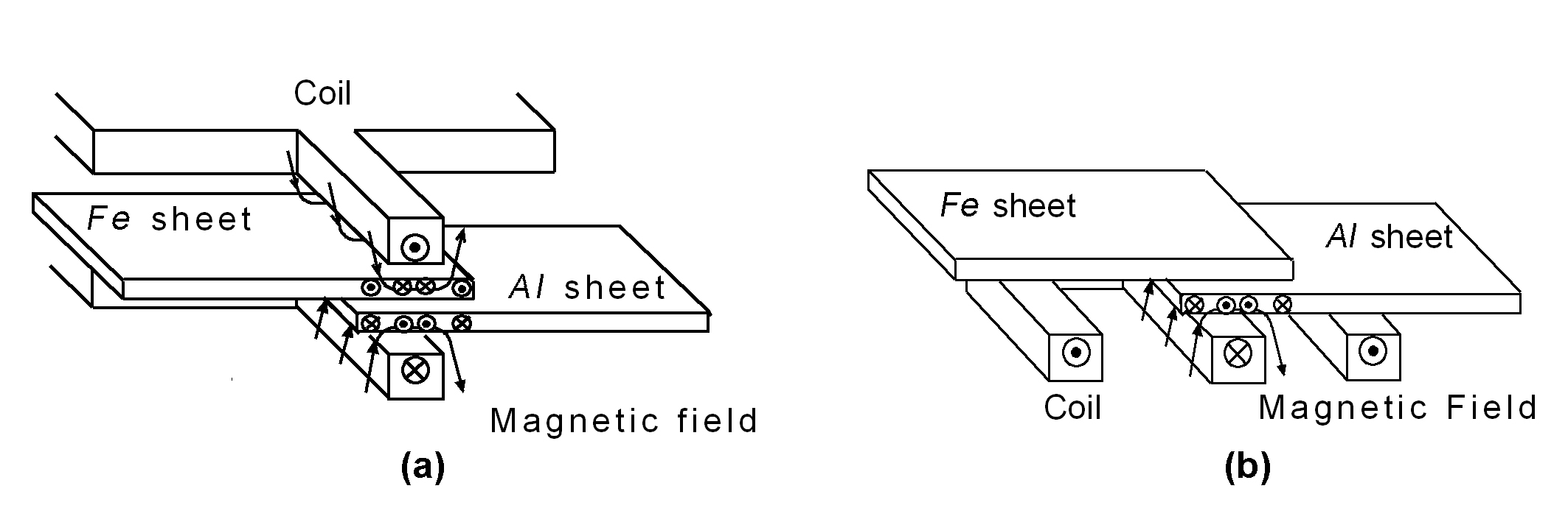
Figuer 1 Principle of MPW The principle of the magnetic pulse welding method was shown in Figure 2 for one Al/Fe sheets sample. When a high current is applied to coil, a high magnetic flux density B is suddenly generated and penetrated into Al/Fe sheets, then the eddy currents (current density i ) pass through them to hinder its further penetration. As a result, an electromagnetic force of i ×B acts mainly on the Al sheet and the Al sheet is accelerated away from the coil and collides rapidly with the steel sheet. At the moment of collision the colliding surfaces can be cleared by a large kinetic energy getting before the collision. After the collision, the cleared surfaces are being pressed together by electromagnetic force and a fixture.
Figuer 2 The eddy current i and the magnetic pressure p are given as following:
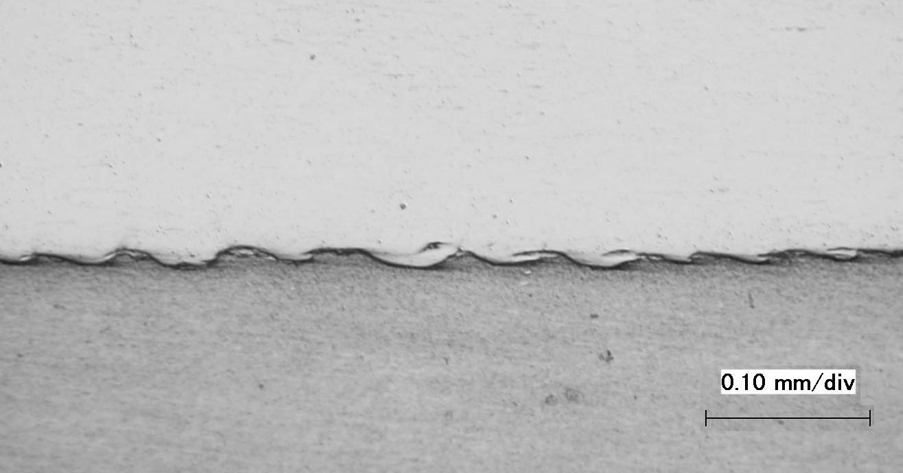
Some Experimental Results 1) SEM Pictuers of welded zone The SEM image of the welded zone in a Aluminium alloy(A6016) and SPCC welded sample is shown as a exmple in the following pictuer. It shows that the wavy morphology bond interface was formed in interface layer without any significant heat-affected zone (HAZ).
(a) Cross-section image of welded sample (the --- zone is the observation area by SEM) (b) SEM image of joined interface for A6016/SPCC sample (SEM images has been prepared by Dr.Kumai in Tokyo Institute of Technology)
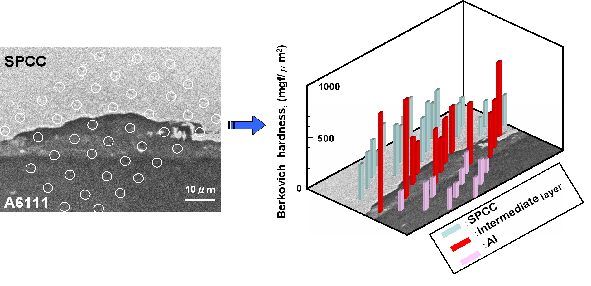
2) Microhardness Profile The following Figure shows the interface microstructure along with traces of the Berkovich nano-hardness indentations for A6111/SPCC sample. The hardness measurement across the interface layer clearly shows that the hardness of intermediate layer is higher than Aluminum base metal in all points. The reason of this higher hardness at the intermediate can be resulted from intense plastic deformation due to high velocity collision or to fine-grain microstructure which was formed by rapid solidification of welded interface.
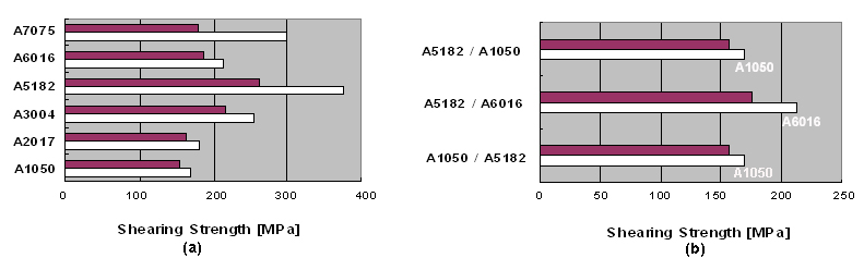
Typical microstructure of the interface layer of A6111/SPCC sample, including Berkovich hardness indentation across the interface (The hardness test has been done by Dr.Kumai in Tokyo Institute of Technology) 3) Tensile Shear Test The comparison of the maximum tensile shearing for same alloy combination (see following Figure) shows that except of A5182/A5182 and A7075/A7075 joints, the maximum tensile shearing for all other case is nearly same as a tensile shearing strength of base metal without weld and for different alloy combination (see(b)), the maximum tensile shearing strength of welded sample also is same as a weaker base metal value. It can be pointed out that the sheet metals retain their original properties without the heat-affected zone (HAZ) problems during weld process and the welded zone is stronger than the weaker base metals so failure always occurred outside of welded zone for these combinations. These results would be expected for a solid-state bonding process.
Comparison of the maximum tensile shearing strength for (a) the same Aluminum alloy combination and (b) different aluminum alloy combination:q the maximum tensile shearing strength of welded sample r the maximum tensile shearing strength of the based alloy without weld. Our experimental results show that the weld joint is always stronger than the weaker metal and in all tested combination a discontinuous or continuous pocket-type, wavy transition layer was formed without any significant heat-affected zone. The capability of our MPW method has been also examined for several other types of metals joint, such as T-joint, circular joint, long sheet sample (up to 500mm) successfully.
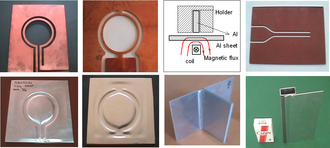
Application of MPW using several types of coil :The upper shows the coil structure and the lower side shows the welded sample.
|

 and
and 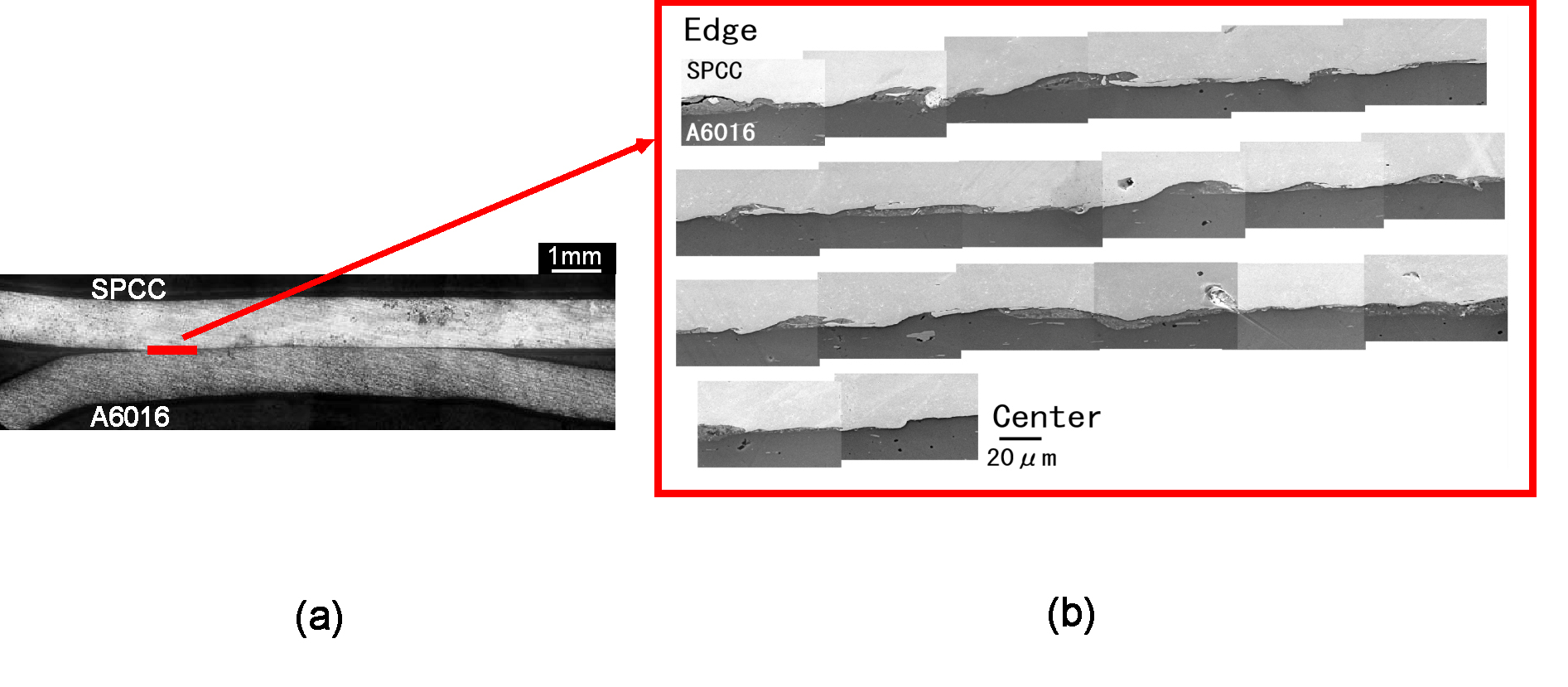
Copyright©MPW-lab., 2007 All Rights Reserved